There's only so much testing you can do before you have to bite the
bullet and plug it in.
There are some detailed test plans but frankly, I couldn't be bothered with all that. I was keen to see if my amp worked. I did at least take the precaution of powering up for the first time with no valves.
All OK.
Added all valves, powered main switch.
All valves glowing nicely. Waited a couple of minutes.
Moved standby switch to "on".
HUGE HUM.
After powering down and unplugging the amp I put it back on the bench and looked for any wiring problems. After about two minutes of staring I saw what I'd missed - the ground wire for the cap can wasn't connected to the star ground, it was just curled under the turret board. Whoops! Stripped, tinned and soldered then time for a retest.
NO HUM.
Right. Time for the signal test. Plugged guitar into normal channel, edged up volume carefully...
NO OUTPUT.
Bollocks. No time for any further investigation so powered down amp. Paranoia sets in. Could be a dodgy valve (can be eliminated by swapping them round) or could be something more serious - like the most expensive component of the amp, the output transformer, which can't even be replaced as the boutique maker doesn't make them anymore...
Friday, 31 May 2013
Thursday, 30 May 2013
Testing - Continuity point-to-point
This is a useful test to do with a print out of the layout. Work from one side of the amp to the other and trace the wire runs. Test for continuity from the furthest possible points, like the valve side of the valve socket right back to the leg of the component on the board, shown here:


Testing - Continuity / Non-continuity
There are some vital tests that you can do with your multimeter on the continuity / diode check setting. It helps if it has an audible beep to indicate continuity.
This is fairly crucial:

This is fairly crucial:

If you don't have continuity between the earth prong of the plug and the chassis (and also the shield connection of a guitar lead plugged into any of the jacks) stop now and fix it!
It's also wise to test all adjacent turrets and adjacent valve pin connections for continuity, just in case of "whiskers" shorting out the connections (you shouldn't get these if you've properly tinned your wires, but it's worth checking). It's worth disconnecting the positive valve heater wire from the transformer for this test otherwise the valve heater pins on the power valves will show as shorted, due to the low impedance of this wind of the power transformer.
Tuesday, 28 May 2013
Still on the line (II)
I found some modern cable with a brown fabric weave over the top, for the vintage look. The trick to stripping it is to wrap a piece of masking tape round it then cutting through the tape. Otherwise the fabric covering goes everywhere.

This connection is quite important. One not to forget.


This connection is quite important. One not to forget.

Wiring in the turret board (pots and ground bus)
Once the valve holders were done, I started on the other side.

Again, there's no real trick to it. It's easy to get blind to wires though - look at the black wire from the volume pot (LHS of photo) that I completely missed.
Some of the mustards looked a bit exposed so I found some mustard coloured heatshrink for the legs.


Again, there's no real trick to it. It's easy to get blind to wires though - look at the black wire from the volume pot (LHS of photo) that I completely missed.
Some of the mustards looked a bit exposed so I found some mustard coloured heatshrink for the legs.

Wiring in the turret board (valve holders)
Finally. The big job.
Starting with the valve holders (note the cut wires and trimmed ends building up at the bottom of the chassis).

There's no real secret to this. Just work methodically, think about where the wires are going to run (direct like the shielded stuff or against the chassis like the teflon wire) and double check it's going to the right place before you cut, strip, tin, solder and trim. Repeat about eight times for each valve holder.

The Cable Tie
The first of many, I suspect.
The unused secondary OT wires (for the 4 and 16 ohm outputs) were getting the way so I zip-tied them under the chassis. I probably don't need them but I think it would be short-sighted to snip them off completely. I'll probably cable tie them neatly inside the chassis when it's all finished.

The unused secondary OT wires (for the 4 and 16 ohm outputs) were getting the way so I zip-tied them under the chassis. I probably don't need them but I think it would be short-sighted to snip them off completely. I'll probably cable tie them neatly inside the chassis when it's all finished.

Sunday, 26 May 2013
That sinking feeling
Soldering onto the ground bus is quite tricky due to the thickness of the wire. Even with my relatively decent soldering iron, it involves heating the joint for 3-4 seconds to get it to the right temperature, which is greater than the ideal two second maximum for a joint.
For a more technical explanation of relative thermal mass, here's 80s American Soddering Guy:
I'm not worried about heating bus wire or any of the teflon wires attaching to the ground bus, but I really didn't want to overheat the vintage mustard cap that connects directly to the bus. The solution is to use a crocodile clip as a heatsink:


The croc clip conducts all the heat away from the cap and removes any chance of overheating. Simple, cheap and effective.
Thursday, 23 May 2013
Tickling round the edges
No real progress this evening, just a bit of prep for the final push.
Added the wires that will go from the pots to the ground bus (and fixed the cap that was going to the wrong lug of the volume pot on the tremolo channel). Still need a bit of thin bus wire from the tremolo channel input jacks to the main ground bus.

Turret board fully wired and bolted in place:

I did a bit of retwisting of the valve heater wiring and I'm a bit happier with the main run of it now. Now just need to find a way of holding it in place. All the wires from the turret board are in place and run approximately to the right valve / pot. Spotted a wire I've missed from the normal channel vol pot to C1 which will be a bugger to add. Glad I spotted it though.

Ready for the final wiring at the weekend.
Tuesday, 21 May 2013
Output Transformer Primaries - doing the math(s)
The only information I had about the output transformer was the following:
OT:
8K Ohm primary impedance
4 Ohm secondary (yellow)
8 Ohm secondary (green)
16 Ohm secondary (orange)
Which is helpful enough for the secondary wiring going to the speaker jack, but wasn't much help for the primary wiring. On the other side I had three wires: red, brown and blue.
Knowing a little bit about push-pull amps, I know that one of these wires is a centre tap that's going to go to the can capacitor and then back to pin 3 of the rectifier valve (via the standby switch). On most of the layouts I've seen, that's the red wire. The other two primaries need to go to pin 7 of V5 and V4.
Knowing that the primary impedance is 8k ohm, I broke out the trusty multimeter and measured the impedance between all three pairs of wires. (I knew it was never going to be bang on 8k for various reasons, but the connections to the centre tap would be half the impedance of the other pair.)

If you can read my notes, the results were:
Brown - Blue 0.588
Brown - Red 0.283
Blue - Red 0.303
So red is definitely the CT. Good to know. I believe there's a chance I'll get an out-of-phase squeal if I get the other primaries on the wrong power tube, but it's a simple enough job to swap them round. I've got a 50% chance (and Vin, the kit designer, has pointed me in the right direction - brown V5, blue V4).

Monday, 20 May 2013
Greenback (part two)
Simple, but needed doing. The speakers were in the wrong orientation for the most effective wiring so I removed the back panels from the cab and rotated the speakers by 90 degrees to line up the contacts. I meant to put one of them on the scales while I had them out - they certainly live up to their "H" designation. Interesting to note that they're made in Thames Ditton (about ten miles down the road from me) but have been all the way to the Netherlands and back (and who knows where else on the way...)

The speakers are 15 ohms each, so by my calculations, if I wired in parallel should be good for the 8 ohm output on the OT. I think. I got some square white speaker wire from Barry at AmpMaker (one wire in the pair is identifiable by the raised braiding down the side which I used for positive). As Barry points out on his site, if you always use square wire for speakers and round wire for instruments, then you'll never get the two mixed up.
While I was there I put the chassis with valves in place to see how it all lines up.


And with the back panels in place:


The valves look a little exposed, but the preamp ones will have the covers on when it's done. Looks almost finished!
Rectification
Like me, when you're contemplating rectification, you probably only think of solid state or valve, right? Something like this:

Or maybe this:
 But there is another type.
Mercury arc rectification is by far the most impressive:

The two glowing orbs on the right are the mercury arc rectifiers at Kempton Steam Museum and convert 3 phase 415VAC into 200VDC @ 100A. Impressive, but possibly a bit big for my amp.
Or maybe this:

Mercury arc rectification is by far the most impressive:

The two glowing orbs on the right are the mercury arc rectifiers at Kempton Steam Museum and convert 3 phase 415VAC into 200VDC @ 100A. Impressive, but possibly a bit big for my amp.
Completed turret board wiring
A flurry of activity on Sunday afternoon started with the completion of the turret board wiring:


I've allowed plenty of wire for connecting to valves, pots, etc. Probably too much as when I was estimating the lengths I assumed I'd be running to edges and going at right angles to the relevant terminal - I think that the wires may take a more direct route.

And the view of the bottom:

I've allowed plenty of wire for connecting to valves, pots, etc. Probably too much as when I was estimating the lengths I assumed I'd be running to edges and going at right angles to the relevant terminal - I think that the wires may take a more direct route.
Tinning
Several times during the build I've been tempted to cut corners by not bothering to tin the stripped ends of hookup wire. The results have generally been crap and have often resulted in me having to redo the whole join because it looked untidy or wasn't a good bond.
The easiest way to tin wire is to hold down the soldering iron using something heavy (like the stand, or a trusty pair of pliers):

Then simply touch the wire and the solder to the iron simultaneously and draw the wire across the iron towards the cut end. Remember to leave that thermal gap (of approx 2mm) between the tinning and the insulation, or 80s "sodderman" will come and find you. (Not so important with PFTE wire as it's pretty much impossible to melt.)
And here is an example of a nicely tinned wire (the OT centre tap). Note the insulation gap at the bottom.

And safely soldered in place:

The easiest way to tin wire is to hold down the soldering iron using something heavy (like the stand, or a trusty pair of pliers):

Then simply touch the wire and the solder to the iron simultaneously and draw the wire across the iron towards the cut end. Remember to leave that thermal gap (of approx 2mm) between the tinning and the insulation, or 80s "sodderman" will come and find you. (Not so important with PFTE wire as it's pretty much impossible to melt.)
And here is an example of a nicely tinned wire (the OT centre tap). Note the insulation gap at the bottom.


Thursday, 16 May 2013
Sucka (Pt 2)

Looks a bit surgical, doesn't it.
It's a combination of one of those crappy solder sucker things and a cheap soldering iron. The bit has a hole in it and the idea is to prime the suction pump, heat up the workpiece with the iron, then press the yellow button, sucking and loose solder through the hole in the bit.
Takes an age to heat up and smells of burning plastic. But for £4.95, it does an admirable job of removing solder. Short of a continuous vacuum desoldering iron (£60+) there's nothing better that I've found.
Wednesday, 15 May 2013
Pliers, strippers and snippers
Here's the selection that I use regularly:


Clockwise from top left:
Strippers - a recent purchase. Cheap, feel cheap, but work well.
Big pliers - Wickes special. Good for big jobs or just weighting things down.
Needle-nose pliers - Good for bending loops in wire for turret soldering. Stolen from my pal Tom who's now bought a replacement so I'm keeping them.
Draper multi-snippers / strippers / benders - over-engineered and overpriced. I rarely use them.
Stripper / side cutters - crap for wire stripping and poorly made (this is the second set after one of the cutting blades sheared off the first one). I've not found a better pair of light duty side cutters though. Great for trimming components legs from PCBs when you want to get a really neat finish.
Wiring the Power Transformer (Big Iron Part V)
Finally I've tackled the power transformer wiring. It wasn't difficult, just fiddly. There's nothing massively complicated about cutting eight wires to length, stripping, tinning and soldering them to something else, but getting it to look neat, getting the twists in the right place, and generally not f'ing it up took a bit of concentration.
After all, if I fuck this up then something's going to go pop. Possibly me.

After all, if I fuck this up then something's going to go pop. Possibly me.

1973 Master Reverb 18w Combo
If the 1973 Lead & Bass Combo is as rare as hens' teeth, then the 1973 Master Reverb 18w Combo is the proverbial rocking horse shit.


I can't find any other pictures anywhere on the web. From the looks of it, it's lost the tremolo channel and it's using the valve in the V1 position for the reverb drive / recovery. (According to Dr Tube it's an ECL86.)
Intriguing. With just a couple more pictures, I could almost figure out how it's all wired together.
How a valve is made
This is a fantastic video about the manufacture of valves in the Mullard factory in Blackburn.
It starts with an description of the parts that make up a valve and runs through the entire manufacturing process.
At 15:32 there is a view of the automated ECC82 assembly line.
21 minutes in there's a explanation of how the valve bases are made and some fantastic automatic glass melting / forming machinery.
I also like the lack of dumbing-down in this film, and the assumption that the viewer is intelligent and informed. How many Discovery Channel programmes would dare to use the line:
"You will remember that during the manufacture of the heater wire, the fine tungsten filament was wrapped around a molybdenum core which served as a mandrel during the winding and as a support during the subsequent operations."
Brilliant!
Wednesday, 8 May 2013
Normal channel shielded input wiring
Extremely fiddly. Made worse by the fact that the chassis is bloody heavy now I've got the power transformer in there. I should really take that out until I've done everything else.
Pleased with the result though. The shielded cable has two cores so I used one each for the hi and lo inputs. Hope that's not going to cause problems.

Pleased with the result though. The shielded cable has two cores so I used one each for the hi and lo inputs. Hope that's not going to cause problems.

Power Transformer Wiring (Big Iron Part IV)
After some discussion about the valve heater wiring connectors, me and Vin* (the guy who designed the kit) agree that this is the correct wiring for the power transformer. If you disagree, please leave a comment before I get round to plugging it in!
Left, top to bottom:
red - HV secondary TO V6 PIN1
red - HV secondary TO V6 PIN7
grey - HV primary TO MAINS (NEUTRAL)
yellow - 6.3V rectifier filament secondary TO V6 PIN4
green - 6.3V filament secondary TO MAIN VALVE HEATER WIRING
Right, top to bottom:
red/yellow - HV center tap TO GROUND
black - HV primary TO POWER SWITCH MAINS (LIVE)
yellow - 6.3V rectifier filament secondary TO V6 PIN5
green/yellow - 6.3V filament center tap TO GROUND
green - 6.3V filament secondary TO MAIN VALVE HEATER WIRING
*Don't worry Vin, I won't hold you responsible
That shrinking feeling
My trusty Iroda soldering iron / heat gun. (I might do a post on tools at some point.)

A couple of bits of heat shrink on the legs:

And in situ, ready for soldering.

Looks quite neat. And prevents anything shorting on it. The excellent Doctor Tweak sells a variety of colours in a handy bundle

Monday, 6 May 2013
Big Iron (Part III)
OK, I'm having a slow day.
How do the connections on the diagram (left) match up with the PT instructions (right)?

How do the connections on the diagram (left) match up with the PT instructions (right)?
Input jacks
Input jacks with the 1M resistors.
The trick is to solder the 1M resistor in place at the bend, return to the chassis and solder in the connecting bus wire, leaving the tags that are going to have signal or ground wire attached unsoldered until later.
That was the approximate plan, anyway.


The trick is to solder the 1M resistor in place at the bend, return to the chassis and solder in the connecting bus wire, leaving the tags that are going to have signal or ground wire attached unsoldered until later.
That was the approximate plan, anyway.


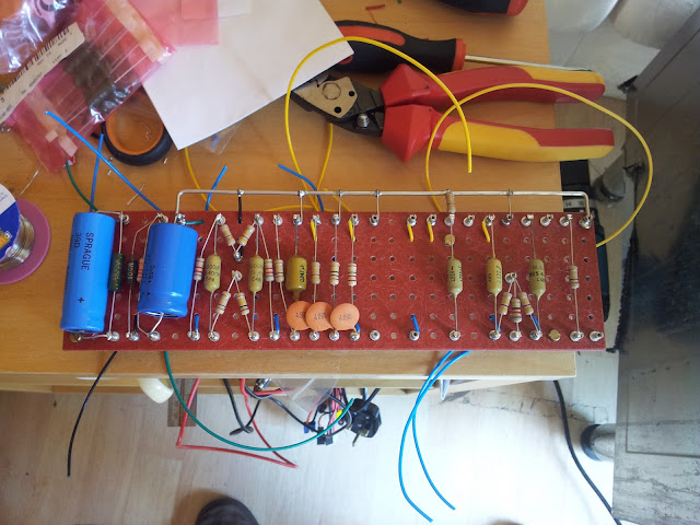
Turret board with some wiring
Almost completed turret board and wires. Just missing a couple of resistors and caps now, and a couple of wires. Looks quite neat!


Power resistors
These 7w 120 ohm Sfernice power resistors are lovely. So much nicer than the shitty white plastic ones you get. The schematic calls for a 125 ohm resistorh, and 120 ohm is easily within tolerances, but seeing as I ended up with ten of them, I decided to test them all and see which one was closest to 125. Sad but true.


Missing components
Unless you love subsidising Royal Mail, check which components you need to buy before ordering, and order them all at once.
I'm still missing a 5w 1k5 resistor, 68k and 47k 1w signal resistors and a 47uF 25v cap.
Oh, and I'm a bit short on yellow hook up wire.
Be organised - do an inventory and order it all at once.
I'm still missing a 5w 1k5 resistor, 68k and 47k 1w signal resistors and a 47uF 25v cap.
Oh, and I'm a bit short on yellow hook up wire.
Be organised - do an inventory and order it all at once.
Saturday, 4 May 2013
Heater wiring disaster
A heady mixture of incompetence and using inappropriate components has resulted in some disappointingly untidy heater wiring.
The first mistake I made was not twisting the wire enough. When a pair of wires is properly twisted it has a certain feel to it and acts like a single piece of wire. In the first couple of attempts, I couldn't get the teflon wire to this level of twistedness, mainly because it kept slipping out of the drill! This meant that the pair of wires looks slightly irregular and untidy, and it came untwisted easily when I was working with it.


The second mistake was using teflon wire at all. It's an absolute pain to get it to stay in position when you bend it. I'm going to have to work out a way to secure it to the chassis at strategic points.

For the last run, I actually managed to clamp the wire in the drill properly and got a decent twist. The question is - do I go back and re-do the whole lot? Or do I let it annoy me forever (until I forget about it)?
Subscribe to:
Posts (Atom)